 Thaka.Ai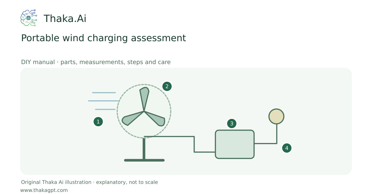
Reviewed 17 October 2026 · schematic not to scale
Assess a complete small turbine with its matched controller, braking and support system. This is a specialist selection route, not a printed-rotor survival build.
- 1Measure wind at the proposed rotor location
- 2Guarded rated device on approved support
- 3Matched control, braking and protected storage
- 4Measure output; keep clear of the rotor
Site and operating requirements
- Measure wind at the intended height; check turbulence, setbacks, tower access, land permission and local requirements.
- Use the complete current designer plan for one rotor/tower configuration, including braking, furling and electrical control.
Tools and measuring equipment
- Anemometer, torque tools and energy logger
Output and operating conditions
Example only: rotor diameter 1 m, air density 1.225 kg/m³ and assumed coefficient 0.30 give about 18 W at 5 m/s but only 3.9 W at 3 m/s, before further electrical losses.
Original calculation with P = 0.5 × air density × swept area × speed³ × coefficient. Actual charging depends on measured power curves and site turbulence.Parts, quantities and dimensions
| Part | Quantity | Specification / dimensions |
|---|---|---|
| Complete small wind turbine | 1 | Documented power curve, operating wind range and matched rotor. |
| Matched control and braking system | 1 | Battery compatibility, diversion load and shutdown as required for the turbine. |
| Approved support and anchors | 1 set | Height, clearance and guying follow the complete equipment design. |
| Anemometer and energy logger | 1 each | Measures hub-height wind and delivered Wh. |
Preparation and component checks
- Check land permission and weather restrictions.
- Review a documented shutdown procedure.
Procedure
- 1
Estimate essential load and consider quieter solar-first alternatives.
- 2
Measure wind at the intended hub height and location.
- 3
Select a complete matched turbine/controller/support combination.
- 4
Have a competent specialist check anchors, clearance, braking and wiring.
- 5
Test commissioning and safe shutdown away from people.
- 6
Log actual Wh and stop within the specified weather limits.
Ready-to-use checklist
- A specialist has checked the support and control route.
- No unsupported printed rotor or safety-critical part.
Safety and inspection
Do not mount above occupied tents or improvise blades, tower joints, braking or guy anchors. Thunderstorm ridges and gusts are unsuitable operating conditions.
Verify the result
Use wind measurements at the real hub height and compare logged Wh against the turbine curve; demonstrate safe shutdown before the trip.
Measurement log
- Wind speed distribution and delivered Wh
- Anchor inspection and shutdown test
Maintenance and repeat checks
- Inspect blades, fixings, guys and cable chafe before every deployment.
- Shut down and pack away ahead of storms according to the complete system procedure.
Troubleshooting
- No output, abnormal heat, noise, vibration or leaks
- Stop and isolate first. Check the documented input, load compatibility, alignment and connections; keep guards fitted and refer specialist systems to their installer.