 Thaka.Ai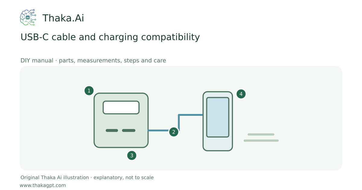
Reviewed 17 October 2026 · schematic not to scale
Reduce duplicate chargers by checking one compatible low-voltage charging system for phones, lights and supported laptops.
- 1Intact protected assembled battery
- 2Match port, cable and load requirements
- 3Keep charging dry and within temperature limits
- 4Measure delivered energy and retain reserve
Site and operating requirements
- Identify the external energy input and the maximum permitted rotor, bearing and spring limits from the selected kit.
- Use a stable dry bench, guards and a clear stop procedure. Do not increase speed to chase a voltage reading.
Tools and measuring equipment
- USB-C meter and device specifications
Output and operating conditions
Example: a device requesting 20 V × 3 A needs a compatible 60 W path. A USB-C shaped plug by itself does not establish that capability.
Electrical arithmetic based on the negotiated voltage and current. Source, cable and device must support the same required profile.Parts, quantities and dimensions
| Part | Quantity | Specification / dimensions |
|---|---|---|
| Compatible power source | 1 | Documented per-port profiles and total simultaneous power. |
| Power-rated USB-C cable | 1 per device | Rating at least the intended power; correct electronic identification where required. |
| USB-C power meter | 1 | Supports the required profile without restricting negotiation. |
Preparation and component checks
- Check total power when multiple ports operate.
- Read the cable power rating.
Procedure
- 1
List each device voltage and power requirement.
- 2
Match the source output profile to the device.
- 3
Choose a cable with the needed power rating.
- 4
Test each connection individually.
- 5
Test the actual simultaneous multiport combination.
- 6
Label the working leads and pack a spare for essential equipment.
Ready-to-use checklist
- No improvised voltage-forcing adapter.
- Every critical device works in the planned combination.
Safety and inspection
Do not use passive connector swaps to force unsupported voltages. Do not assume every multiport rating is available at each port simultaneously.
Verify the result
Test all planned simultaneous loads and confirm that reconnecting one device does not interrupt an essential one.
Measurement log
- Negotiated volts, amps and watts
- Combinations that reconnect reliably
Maintenance and repeat checks
- Keep sockets dry and remove grit without conductive tools.
- Replace leads that disconnect intermittently, fray or overheat.
Troubleshooting
- No output, abnormal heat, noise, vibration or leaks
- Stop and isolate first. Check the documented input, load compatibility, alignment and connections; keep guards fitted and refer specialist systems to their installer.